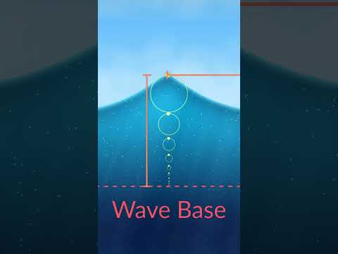
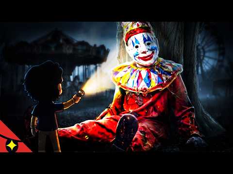
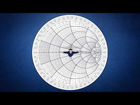
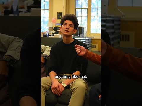
DIY RF Detector Step by Step build | Breadboard #3
Advertisement

LEAVE YOUR COMMENT

LATEST COMMENTS

@gunnerdavidson7287 Says:
Thank you so much! I was really bored and in need of something interesting to do and this was amazing! The way you described the circuit along with your instructions were very clear! Thank you!
@Manaswini0507 Says:
This is great! Can it be used to detect hidden cameras too???? Please reply
@NZhTI Says:
I have Speaker A Sound and Meter
@tanveernaeem1157 Says:
What is the detectable frequency range of this detector. Thanks.
@nildocarvalho1471 Says:
Awesome! Thisn detected a running out dog?
@itsheiko3549 Says:
0:34 an OpAmp "LM358" is needed
@jaiminpatel4231 Says:
Hey my LED is always on can anyone help what I did wrong here?
@harlock0974 Says:
Hello ! I successfully built a 40 kHz detector using your circuit. The antenna is an inductor coil and a capacitor tuned to this frequency. I used a TLV2462 as I don't have the LM358. I don't have neither germanium diodes so I directly connect the antenna to the Op-amp pins. I loose the negative part of the signal but it works anyway. The range is very short (<10 cm) so may be I'll add a second amplification stage to improve this. But I don"t understand well the theory behind. As the minus pin isn't connected to a positive voltage through a large resistor (as usual with Op-amp comparators), the voltage reference is zero ?
@sivanathv9868 Says:
I have setup the exact circuit, but there is no rf detection. Every components are working fine. Could anyone please help me out!! @The Science Furry
@leagueofotters2774 Says:
Will any lm 358 work? 358P, D, M, AD ?
@RubenMusic_s Says:
Funciona muy bien..
@YogeshKumar-im4qw Says:
,this projekt ten feet range honi chahiye।
@YogeshKumar-im4qw Says:
इस डिटैक्टर की रेंज कैसे बढ़ाएं।
@stanningeveryone7811 Says:
hello sir. great tutorial. I would like to refer this for my project. my question is, can it also detect the activated RFID tags, the one which already programmed or it can just detect the tags (inactive one/not programmed)?
@kevinje3971 Says:
Hi, I am confused, why is my led is always on? And why do you need 1M resistor on the non inverting side of op amp and small value on the value of op amp?
@chatgptrevolution Says:
How can we make something specific to detect 101.4 khz frequency that they use for Telecom marking underground?
@albin6382 Says:
I hate furries, but nice video.
@sayfahstarlightlunar8453 Says:
You can use ic lm393n. Because very sensitive. https://youtu.be/d07sCFTsMLc
@guilherme6374 Says:
Is not possible to use 1n4148 in the place of 1n34 diode?
@daloarabagummoni4746 Says:
Do we add this Saket with ardunio uno??
@manipulativer Says:
Yo! Is there a frequency range in which this thing works? I need it to work up to 60Ghz and if its possible to make it more sensitive with different resistors maybe?
@nextnext8902 Says:
Hello, i have done as you said. But my led light is always on. What can i do? (Edit: After this, i have removed diodes and led light still always on) (mine is Lm358L)
@techycharles Says:
❣️❣️❣️
@kenweeks8039 Says:
Hello again! I have now made an RF detector to your specifications, the idea being to use it to test car RF keyfobs/keycards. It works! Very pleased with the result, although it can be a little tricky sometimes to hold the antenna in the correct 'sweet spot' against the car key fob/card for it to work correctly. One thing that occurred to me when testing the detector - how long should the antenna wire be for best sensitivity? Could the antenna wire sensitivity/reception be improved by coiling it up several times?. When testing the detector with a small hand held (bike to bike) radio, the detector led lights up from several metres away, whereas, a car key fob/card has to be held against the detector for it to work, so I thought that this may be due to the length of the antenna? Many thanks again for your video, Ken.
@fifaham Says:
Also we can use Darlington transistor (High Gain) along with RC circuit connected to the antenna and then series that with another Darlington and produce same action.
@fifaham Says:
You may add a fixed inductor and a variable capacitors in parallel (multi capacitor banks) (parallel LC circuit > tuner) so you can tune into various frequencies to detect, anywhere from most low to the unity gain (MAX frequency capability of Op Amp) - add this circuit between the bottom of antenna and the the point where two diodes connect.
@kenweeks8039 Says:
Hi, do you think this would work for testing a car's remote control (RF) key fob/card? Thanks, Ken.
@marcelsolferre3614 Says:
Nice job, it would be nice to measure the signal in hertz format, maybe sending it to the smartphone (frequency counter app)
@miguelbautista9250 Says:
Que margen de frecuencias puede detectar?.
@jankristijan5889 Says:
will this work on 4.5V?
@jackevans2386 Says:
Hi, So 1N34 diodes will work OK up at 2.4 GHz ? cheers
@jamesmcbrideag5ve743 Says:
I tried the your circuit just as you built it, but with a 4558 instead of LM358 (it's what I had on hand). However, when I plug in the battery, the LED is constantly on, no matter where I am located. Any ideas what I'm doing wrong?
@Ibrahim1999 Says:
Hi there , i was wondering about the relation between an antenna's length and the wavelength it can catch , could you tell me ?
@dimitriosa8tsipouras953 Says:
CAN I USE 1N4148? AND NOT 1N34?
@indulgence8860 Says:
So how do you jam signals from the government to not read your brains reflexes.....
@jaricomusic1604 Says:
Thank you! Please keep the videos coming. Love the work . Definitely subscribed
@ChristianvonHausen Says:
hi, first thx for sharing. can the LM358 be set to detect a specific RF or Frequency?
@naersthebat4129 Says:
ah yes... a fellow science fur...
@volkinaxe Says:
that`s a cool thing good job

More Videos